4 - Implementing Adaptive Data Rate
Adaptive Data Rate (ADR) describes the scheme whereby the network server controls the data rate, RF transmit power, and channels an end device uses when sending uplinks, as well as the number of retransmissions made.
The network server uses the Received Signal Strength Indicator (RSSI) of the messages received from the end device to determine how close the end device is to the nearest gateway(s). This allows the network server to select the most appropriate settings for each end device.
The benefits of ADR are that it helps preserve the battery life of an end device and reduces interference, giving all end devices on the network the best chance of communicating successfully.
ADR Backoff
As soon as the end device is no longer using the default TX output power, data rate, channel plan, or NBTrans, implement ADR backoff.
Note
Even if the device is mobile and does not implement ADR, the channel plan can still be modified using the LinkADRReq, so ADR backoff must still be used.
There are three variables referenced throughout the process that you need to store and update on the end device.
-
ADR_ACK_LIMIT: The number of times an end device should tolerate sending an uplink to the network without receiving a response is defined as ADR_ACK_LIMIT. After the end-device has sent ADR_ACK_LIMIT number of uplinks without receiving a response from the network server, it must set the ADRACKReq bit on further transmissions, requesting a response from the network server. The ADR_ACK_LIMIT value is defined as 64 in Section 2.3, ‘Default Settings’ (page 28) of the RP002-1.0.4 LoRaWAN® Regional Parameters specification.
-
ADR_ACK_DELAY: The end device will set the ADRACKReq bit on uplink transmissions after it has sent the ADR_ACK_LIMIT number of uplinks without receiving a response from the network server. The network server is then expected to respond within ADR_ACK_DELAY uplink frames, defined as 32 in Section 2.3, ‘Default Settings’ (page 28) of the RP002-1.0.4 LoRaWAN Regional Parameters specification.
-
ADRACKCnt: The ADRACKCnt field is used to count the number of uplinks sent by the end device before receiving a downlink message. Initially, it is set to 0.
Note
LoRaWAN 1.1 allows the ADR_ACK_LIMIT and ADR_ACK_DELAY to be defined by the network server and passed to the end-device during the OTAA process. MAC commands exist to change the value of ADR_ACK_LIMIT and ADR_ACK_DELAY, using ADRParamSetupReq and ADRParamSetupAns, so these must default to 64 and 32, respectively, and then must update based on the ADRParamSetupReq if implementing LoRaWAN version 1.1.
After the end device modifies the default settings in response to a LinkADRReq MAC command, it must set the ADRACKCnt to 0. Whenever the end device sends a new uplink frame, it must increment ADRACKCnt by 1.
Note
The end device is also required to update its uplink frame counter (FCntUp) on each new uplink frame, described in the Metadata of the Sending Messages Book. Bear in mind that the FCntUp must not be reset to 0 until the end device is reset, whereas the ADRACKCnt must be reset to 0 whenever a downlink is received.
Once an uplink has been sent by the end device, it will open up to two receive (RX) windows to listen for a response from the server. If no response is received in either window, the end device must work through the sequence below.
-
After ADR_ACK_LIMIT (64) uplinks have been sent from the end device without receiving a response (
ADRACKCnt >= ADR_ACK_LIMIT), the end device must set the ADRACKReq bit on each subsequent uplink, as shown in Figure 1. The ADRACKReq bit requests the server send a response.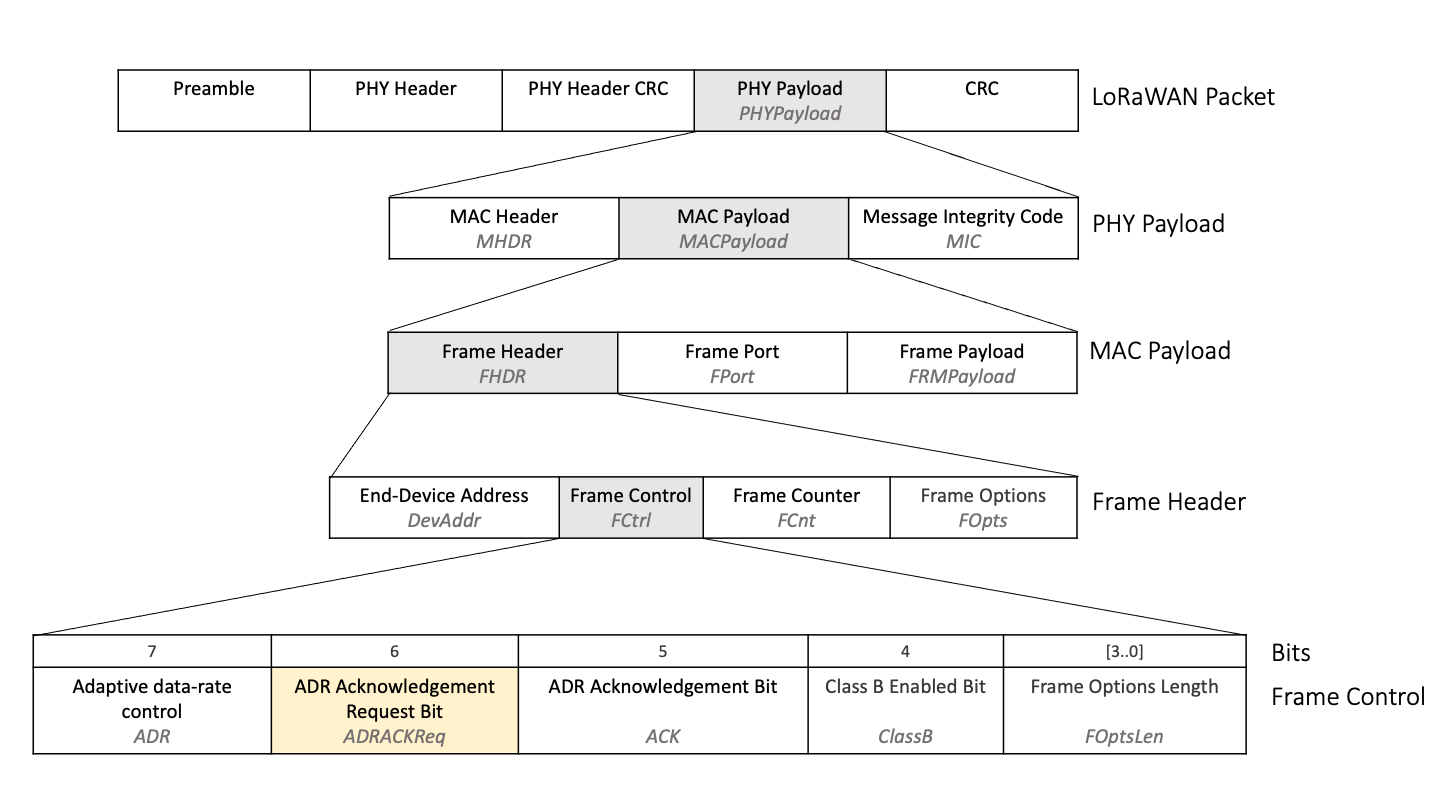
Figure 1: Position of the ADRACKReq bit in uplinks sent from the end device to the network server
Section Uplink Bit Fields of the Sending Messages Book has more information on sending uplinks with the ADRACKReq bit set.
-
After a further ADR_ACK_DELAY (32) uplinks have been sent without receiving a response (
ADRACKCnt >= ADR_ACK_LIMIT + ADR_ACK_DELAY), set the TX Power back to the default setting for the operating region, described in the section TX Power in the Sending Messages Book.Note
The default TX Power is the maximum power level the end device can support that is permitted for the region in which it will operate.
-
After a further ADR_ACK_DELAY (32) uplinks have been sent without a response from the server, change the data rate to the next lowest data rate for the region the end device will operate in, specified in the ‘Data Rate and End-device Output Power encoding’ subsection for the region in Section 2 of the RP002-1.0.4 LoRaWAN Regional Parameters specification.
-
Repeat step 3, stepping the data rate down each time a further ADR_ACK_DELAY (32) additional uplinks have been sent without a response from the server, until the lowest possible data rate is reached. When the end device is operating on the lowest possible data rate, move to step 5.
-
After a further ADR_ACK_DELAY (32) uplinks have been sent without a response from the server, the end device must reset NbTrans to the default value of 1 and then take one of the following final steps:
If the device will operate in a region using a dynamic channel plan; enable the default channels as specified in the ‘Band Channel Frequencies’ subsection for the region in Section 2 of the RP002-1.0.4 LoRaWAN Regional Parameters specification.
If the device will operate in a region using a fixed channel plan, enable all channels.
Note
Check Section 1.3, ‘Regional Parameters Summary Tables’ (page 24) of the RP002-1.0.4 LoRaWAN Regional Parameters specification to find out which channel plan type is applicable to a given region.
The end device will now only transmit each message once, conserving power. All channels are now enabled, the power is the maximum and the data rate the lowest possible, so the device has the highest possible chance of reaching a gateway. As soon as it reconnects, the network will begin to modify the settings again using ADR, reducing the power consumption.
Warning
If at any point the above settings result in an invalid combination of TX Power, data rate, or channel mask:
-
Set the TX Power back to the default setting; the maximum power level the end device can support that is permitted for the region in which it will operate.
-
Reset NbTrans to the default setting; 1.
-
If the device’s region uses a dynamic channel plan; enable the default channels as specified in the ‘Band Channel Frequencies’ subsection for the region in Section 2 of the RP002-1.0.4 LoRaWAN Regional Parameters specification. If the device’s region uses a fixed channel plan, enable all channels.
If the end device receives a downlink at any time during the backoff procedure, reset the ADRACKCnt to 0 and clear the ADRACKReq bit if it is currently being set. This will restart the backoff procedure from the beginning.
The table below shows an example ADR backoff.
|
ADRACKCnt |
ADRACKReq |
Data Rate |
TX Power |
NbTrans |
Channels |
|---|---|---|---|---|---|
|
0 to 63 |
0 |
DR2 |
TXPower 1 |
3 |
Using a channel mask |
|
64 |
Changed to 1 |
DR2 |
TXPower 1 |
3 |
Using a channel mask |
|
65 to 95 |
1 |
DR2 |
TXPower 1 |
3 |
Using a channel mask |
|
96 |
1 |
DR2 |
Changed to default, TXPower 0 |
3 |
Using a channel mask |
|
97 to 127 |
1 |
DR2 |
TXPower 0 |
3 |
Using a channel mask |
|
128 |
1 |
Changed to DR1 |
TXPower 0 |
3 |
Using a channel mask |
|
129 to 159 |
1 |
DR1 |
TXPower 0 |
3 |
Using a channel mask |
|
160 |
1 |
Changed to DR0 |
TXPower 0 |
3 |
Using a channel mask |
|
161 to 191 |
1 |
DR0 |
TXPower 0 |
3 |
Using a channel mask |
|
192 |
1 |
DR0 |
TXPower 0 |
Changed to 1 |
Changed to default channels |
|
193 onwards, until a connection is regained |
1 |
DR0 |
TXPower 0 |
1 |
Default channels |